Cooling Loop – Your Secret Weapon to Create Cooling Channels
If you are a mold designer working on the injection mold, you must understand the importance of designing a reasonable cooling system, which greatly affects production efficiency since cooling takes most of the mold cycle time. Download and try ZW3D
However, cooling system design can be difficult because it’s at the end of the mold design process, before which, designers need to design the cavities, slides, etc. So when it comes to cooling system design, there will be many “obstacles” in the plate.
What makes it even harder is that the design of cooling loops (also called a cooling channel) is tedious.
Usually, you need to go through at least 4 steps.
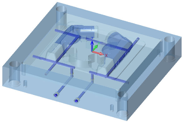
Step 1: Create a sketch or a 3D sketch for the cooling route
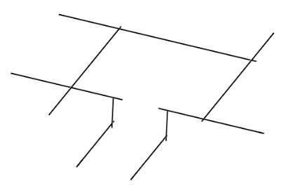
Figure 1. The sketch of the cooling route
Step 2: Along the route, use Swept Rod to create the basic shape of the loops.
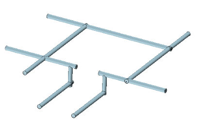
Figure 2. Create the shape of cooling loops by Swept Rod
Step 3: Use Cut command to hollow out the cooling loops on the plate of the core/cavity based on the shape of the rods.
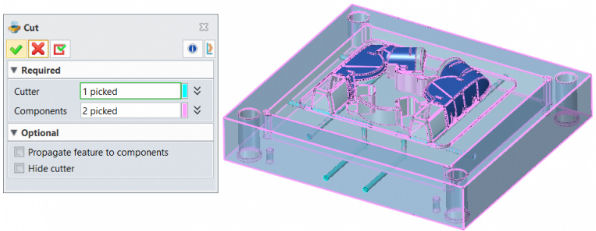
Figure 3. Hollow out the cooling loops with Cut command
Steps 4: Finally, add other cooling components, for example, joints.

Figure 4. Add joints to the end of the cooling loops
So, to finish cooling loops design, you may use commands such as 3D Sketch, Swept Rod, Cut, General (to insert general standard parts), etc. Quite tedious, right? But, the headaches haven’t ended yet. Design changes are inevitable during design process. If you need to change the route or diameters of the loop, it brings more troubles to you.

Figure 5. The tools used to create a cooling loop in the traditional way
In ZW3D 2020, cooling loops can be created with one command
Cooling Loop. You can easily create two types of cooling loop — Single object or Two objects. Unlike the traditional method, you can directly generate the channels by continuously picking points at the locations you want, so you skip the steps like drawing sketches and creating pockets on the plate.
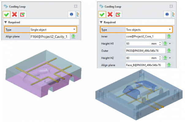
Figure 6. Cooling loop types: Single object and Two objects
What’s more, you can preview the position of the cooling loops dynamically during the creation process, to prevent intersecting with other components in the plates.
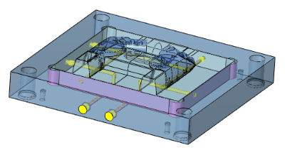
Figure 7. Create cooling channels with dynamic preview
After creating the loops, you can insert other cooling components like joints, plugs and oil rings by Cooling Parts. It allows you to choose the supplier and the type of parts, and to input or adjust parameters like diameter, thread size and safe distance under dynamic preview.
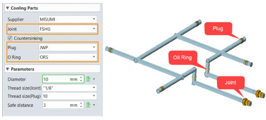
Figure 8. Insert cooling components based your needs by using Cooling Parts
Just by several clicks, the cooling system design is done. The tricky task becomes an easy job.
How about modifying the cooling loop? First, select “Cooling” in Part menu, then right-click the relevant step in the history tree, and you can easily redefine the position and the size of the cooling loops, and also adjust the parameters of other components as introduced just now.
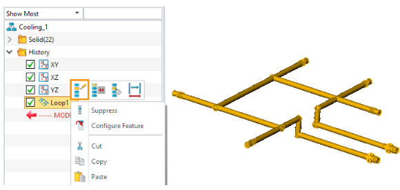
Figure 8. Insert cooling components based your needs by using Cooling Parts
So far, I have shared all the tricks about cooling loop design in ZW3D 2020, which can greatly simplify your workflow. Instead of taking so much time to calculate the route or the position of the cooling loop, you can create one in a more flexible way.
