Three Useful Tools to Facilitate Communication with Manufacturers
Point Table
When you finish the product design and start to prepare the 2D drawing sheets, there are always some special requirements you may want the manufacturers to pay attention to. Normally, you can list the technical descriptions on the drawing one by one, like the figure below shows.
That’s one way, but not the best. As you know, it’s not only hard to use words to describe the exact positions where you’re trying to explain on your product, but also troublesome to match the positions you are annotating with multiple items of descriptions listed elsewhere, easily causing misunderstandings of the manufacturers.
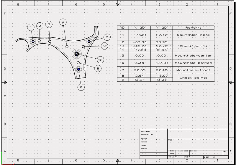
Now with Point Table in ZW3D 2021, you can create a point table to specify any exact positions you want by a few clicks. Follow the simple steps below to create one:
Step 1: Insert points by Point command at the positions you want your manufacturers to have an eye on.
Step 2: Click Annotation under the Layout tab, and box select all the points created.
Step 3: Specify the base point, and give the point table a name.
After that, a point table will be generated and you can place it wherever you want.
In the point table, the ID and position of each point (XY coordinate, based on the base point you select) will be displayed, and you can also add remarks for each point as you need.

Point Table
Dimension Table
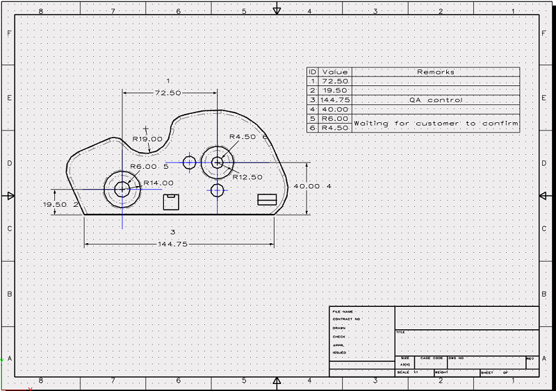
Likewise, Dimension Table is also available for you to attach your remarks to certain dimensions. The steps are similar:
Step 1: Click Annotation under the Layout tab.
Step 2: Click the Dimension Table icon on the right panel.
Step 3: Pick the dimensions you want to highlight and annotate, and give the dimension table a name.
After that, a point table will be generated and you can place it wherever you want. Each selected dimension will be assigned with a specific ID and also its value, so that manufacturers can track the exact dimensions accordingly.

Dimension Table
OLE Object
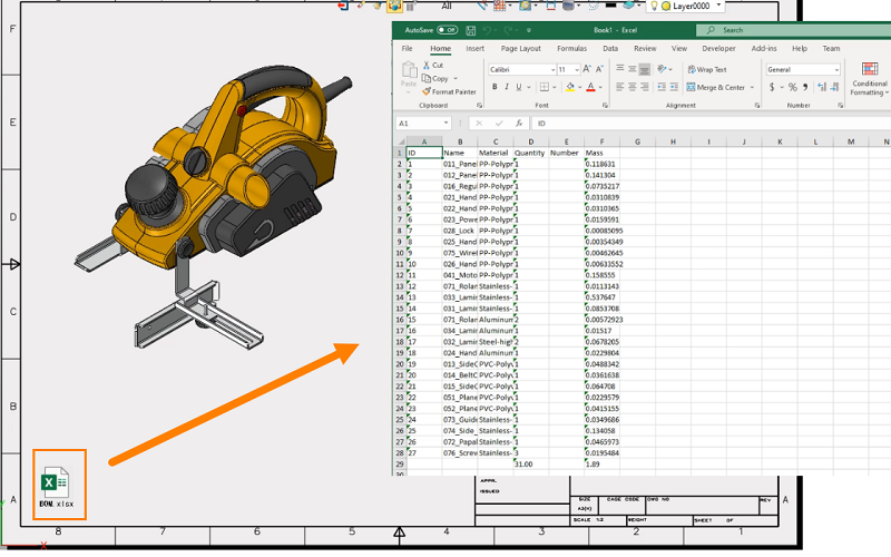
If the above tables still cannot satisfy you, what about PPT, Word or Excel? Yes, OLE Object can now be inserted into 2D drawings in ZW3D 2021. You can just write down anything you want your manufacturers to know in different file formats, and directly attach them to the 2D sheets:
Step 1: Click Object under the Dimension tab.
Step 2: Browse and select an external file you need by “Create from File” in the Insert Object dialog.
Click “OK” and the OLE object will be added to the sheet in the form of an icon. Double click on it to open it.

OLE Object
